In our previous blog, we learned that zero calibrations are influenced by atmospheric pressure. They’re also performed directly after analyzer installations, and provide the following output values:
- Signature gain
- Reactant peak drift time window (RL, RH)
- Target peak drift time window (TL, TH)
- Zero-offset (zero factor) when measuring a sample with no AMC present
Drift times will be higher at sea level than at higher altitudes. The zero calibration algorithm can identify the location of the dopant peak in the IMS spectrum on the x-axis (drift time).
Procedure
Zero calibration is a thirteen-minute procedure, described in the following steps:
- Establish the average baseline current conducted through the ion collector plate (physically located at the end of the IMS cell). Spectrum flattens at this stage.
- As the dopant peak height slowly grows, the analyzer will differentiate the peak from the spectrum background. The analyzer automatically adjusts a digital potentiometer to set the spectrum’s peak height to a certain value. This step takes approximately 2 minutes.
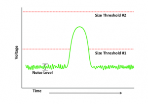
- The calibration algorithm measures all charged ionic species that travel down the IMS drift chamber and contact the ion collector plate. The dopant peak is the only peak present if installation was performed successfully and there is no CDA contamination.
- The reactant drift time window center, upper limit (RH) and lower limit (RL) are defined to correspond to the emerging dopant peak.
- The analyzer looks for the presence of an additional peak when there are charged AMC molecules in the sample stream. This determines the AMC (target) window limits.
- The analyzer can now continuously detect the height of both the reactant and AMC peaks by measuring the local maxima within each window.
- In the final step, the Zero Factor is quantified by taking the final 10-minute average of the target peak amplitude, then subtracting that value from the average background baseline average. The zero factor is subtracted from the measured target peak height for every subsequent measurement.
In our next blog, we look at span calibrations and the steps to perform them. Download the full paper here to read about zero and span calibrations in more detail.
Click here to learn more about innovative AMC monitoring solutions to help you quickly identify problems and their location before your product is contaminated: AirSentry II Point-of-Use Ion Mobility Spectrometer
See links to additional supporting resources below:
On-Demand Webinar: Efficient troubleshooting techniques for AMC monitoring
Application Note: Calibration and Spectrum Troubleshooting
Want to read more? Jump to other released posts in this series:
Part 1 of 4: IMS Spectrum Introduction, Measurement and Calibration
Part 2 of 4: Zero Calibration (You are here!)
Part 3 of 4: Span Calibration
Part 4 of 4: Troubleshooting Abnormal IMS Spectrums
Don’t miss an episode of this series. Register for updates on the right column of this page.
Click here to contact our experts for questions.