In our previous blog in this series, we learned about the many forces that can act on a particle when it travels through tubing. Now, let’s take a look at how we can mitigate these forces on our particle data.
Isokinetic Particle Sampling
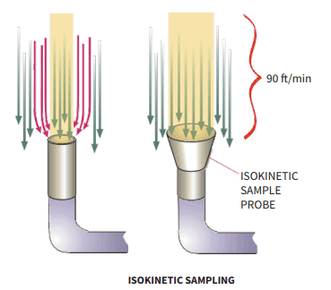
The first way to ensure reliable, accurate data is to use isokinetic sampling inlets. In laminar flow environments, or in ducts leading to a filter, the air is considered to be moving unidirectionally. The sampling of this air flow must neither be over or under the distribution of particles within that flow. This requirement is satisfied when isokinetic sampling is performed. Isokinetic sampling means that the air velocity in the supply air is the same as the air velocity in the particle counter’s sample-tubing inlet.
If the velocities differ, then either a positive or negative sample collection error occurs. An isokinetic sample error increases with particle size, but is not of great concern for particles smaller than 1–2 μm.
Federal Standard FS 209E1 shows that isokinetic sampling errors greater than 5% are not expected for particles smaller than a few micrometers when using a sample probe with inlet diameter of 2 mm or larger, even when sampling and sampled air velocities differ by an order of magnitude. However, when macro particles > 5 μm are to be measured, then isokinetic sampling is required. Particle Measuring Systems has a calculator that accurately assesses the dimensions of the isokinetic probe and the associated errors should a non-standard sample probe be used.
Small Transport Distance
 When a sample is taken for either certification or routine monitoring operations, it is not uncommon for the isokinetic sample probe (ISP) to be in a remote location from the particle counter optics. In this situation, the sample is drawn through tubing to the particle counter. When the sample is to be transported any significant distance in the tube from the point of sampling to the point of measurement, some particle losses will occur in the transport tubing. The losses are dependent on tubing type, flow velocity, tubing diameter and distance. Large particles are lost by a combination of gravitational settling to the bottom of the duct and inertial deposition on the walls of the tubing when directional changes occur. See below.
Small particles are lost to the duct walls by Brownian motion and diffusion effects.
When portable particle counters (such as the Lasair® III 110 particle counter) are used, the flow rate in the tubing is significantly reduced; therefore, the maximum permissible distance is also reduced. The above figure shows a similar pattern to that for manifold sampling, but over much shorter distances.
Tubing Material
Electrostatic forces also account for a proportion of the losses in a sample. Therefore to reduce the effect of these additional forces various types of material were tested in order to establish a suitable standard.
The preference order of tubing material is based on a combination of particle loss rate, electrical conductivity, and potential for oxide or sulfide formation when the tubing is exposed to urban air. From best to worst:
- Stainless Steel
- Bev-a-line
- Polyester (as polyurethane)
- Polyester lined vinyl
- Copper
- High density polyethylene
- Glass
- Teflon
Questions?
Not sure what kind of particle tubing or transport length will work for your application? Ask our industry experts for help and choose the best option without any expensive trial and error!
In our next blog series, we’ll look at acceptable losses that no amount of mitigation will prevent. What are they, and do they have much of an impact? Find out before the week-long wait by downloading the paper here.
Interested in the Lasair® III 110 or another aerosol particle counter? Check out of full catalog of products here.