
Particle Transportation
 Defining acceptable losses for particle transport is difficult, as any loss can be deemed to be unacceptable. However the practical implications of installing sensors on production equipment can be considered, along with the uncertainties and tolerances for particle counters.
The ideal installation of particle sensors would eliminate tubing to avoid losses altogether. But this is not often a practical choice given that sampling locations are often inside production equipment with limited space where a sensor cannot be installed.
When the installation of transport tubing is required, questions arise as to what length of tubing is acceptable and how best to install it.
For particle sensors with a flow rate of 28.3 LPM (1 CFM), a maximum length of 2 meters of transport tubing should be used wherever possible. This guidance is based on establishing a balance between the desire to minimize particle losses and the ability to easily install sensors in proximity of the sampling point.
The study here indicates that 5 micron particle loss at 3 meters of tubing is almost 50%, whereas losses are less than 20% at 2 meters, a significant reduction. Limiting the tube length to 1 meter would certainly yield even fewer losses, but the installation of a 1 meter tube can be difficult or impossible in many applications. This is often driven by the design of the production equipment or the need to avoid interfering with operator movement. When installing transport tubing, there are basic guidelines that should be followed wherever possible:
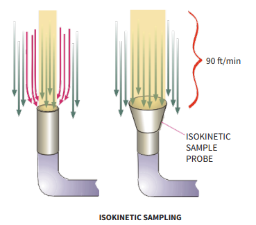
- Use isokinetic sampling probes in unidirectional flow zones
- Minimize tubing bends and avoid sharp bends
- Ground conductive tubing to avoid static buildup
- Install the sensor below the sample inlet and avoid ‘uphill’ sections of tubing (use gravity to help transport)
Knowing that some levels of particle losses are inevitable with transport tubing, many users of monitoring systems may wonder whether to adjust or correct their data. First consider that even without transport tubing there are inherent uncertainties and tolerances for particle counters, as with other optical or electronic instruments. Table 3 shows a comparison of two standards associated with aerosol particle counting.
Biasing of data is dependent on probe orientation, distance apart, air flow patterns, number of particles being sampled, duration of test, baseline variables between counters, optical variances, etc., making the definition of an absolute error difficult.
The data when sampling with transport tubing could be determined as incorrect relative to a result gained using no tubing. There are two methods for the correction of this data.
- If the data is to be determined as an absolute measurement and no tolerance for sample tubing is allowed, but sample tubing must be used to gain a result, the only way of determining the correct data is to multiply the actual data by a correction factor. The correction factor application is not simple however, as particles not of a single size – they are a range of sizes between two sample thresholds. As such, this is a logarithmic relationship (ISO 14644-1) and the data must be integrated between those two extremes for each size.
- A more suitable method for correcting data for monitoring applications is to adjust the alarm limit to reflect the losses in tubing. A 10% or 20% reduction in the alarm limits is simple to effect and does
therefore represent a better reflection of the impact of particle losses.
COMPLETE THE FORM TO DOWNLOAD THE FULL PAPER